UC Digital Futures Building Grand Opening
Big thanks to all faculties and students involved in helping the Digital Futures Building grand opening!
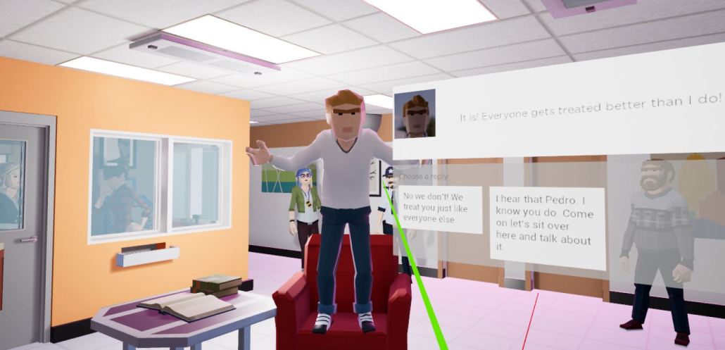
XR-Lab presented research projects on the Grand Opening day on 09/23 to hundreds of guests, along with more than 20 Labs at UC Digital Futures Building. We are very proud to be a member of this striving research community. We look forward the collaboration with industry, government, and community partners and making an effort to solve real-world problems.


using extended reality to solve real-world problems.


News on the Grand Openings of Digital Futures Building:
- Excitement is Growing for the Digital Futures Building’s Official Opening
- UC celebrates Digital Futures grand opening. Research labs to develop solutions to real-world problems
- UC to host Digital Futures grand opening: Facility for interdisciplinary research to celebrate opening Sept. 23
- From the Ground Up: The [Digital] Future is Here
Next Lives Here
The University of Cincinnati is classified as a Research 1 institution by the Carnegie Commission and is ranked in the National Science Foundation’s Top-35 public research universities. UC’s medical, graduate and undergraduate students and faculty investigate problems and innovate solutions with real-world impact. Next Lives Here.